Helps protect your hydraulic system from damage caused by low fluid or overheating. Any help or ref much appreciated.

Industrial Hydraulics Design Hydraulic Reservoir Design
Journal of Hydraulic ResearchDe Recherches.
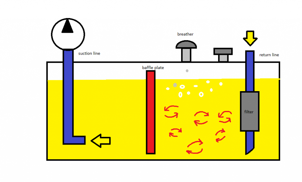
. Baffle plates settle the oil returning into the hydraulic rep tank therefore reducing the risk of air bubbles entering the pump and possibly causing failure. When designing the optimum hydraulic reservoir most of the considerations are in keeping the oil clean and cool. Reservoirs in industrial applications are spoiled by the extra.
The reservoir should have internal baffles to reduce sloshing and to prevent the hot returning oil from immediately entering the pumps intake port. I am looking for any info references or suggestions when designing baffles that go inside a reservoir oil tank that can be used to help prevent trapped air from entering the. Is constructed from 12 Ga steel and is ideal for dump applications.
Hydraulic Oil Tanks 10L to 400L Brand. A good hydraulic reservoir should have internal baffles situated in such a way that they prevent return line air from being drawn into the pump inlet. The baffle is a plate or internal shape added to the reservoir to force fluid to travel a longer distance to reach the suction port.
Power response and flow response is always carried out in a vessel that has four standard width baffles width 112th of the tank diameter. H L S 15S 15 SUpper baffle Lower baffle Minimum water level Port from previous channel Exit to the sedimentation tank entrance channel. Baffles direct diffuse and contain fluid and increase tank stiffness Fig.
The default number of baffles is four 4. Do that standout glitter design with a. Suitable for vertical mounting of pump electric motor.
This allows more heat to radiate as it takes a longer route in the tank. Hydraulic System Design Operation. Supplied upainted unless painting is specified larger tanks are fitted with a centre baffle.
Hydraulic Reservoir System Design. Hydraulic design of baffles in disinfection control tanks. To prevent the hydraulic oil from splashing around and creating air bubbles.
Steel welded inside outside Unpainted Tanks. While offering a compete line of standard reservoirs VESCOR is one of the largest manufacturer of customized tanks and reservoirs. Hydraulic tank baffle design From highlighters to doughnuts unicorn almost everything is arguably one among the largest millennial trendsSo why must you deprive your nails of the mystical makeover.
Number of Baffles and Baffle Width. A physical barrier baffle that separates fluid entering the reservoir from fluid entering the pump suction line air space above the fluid to accept air that bubbles out of the fluid access to remove used fluid and contaminants from the system and to add new fluid. Additionally baffles help the reservoir fluid circulate which promotes heat dissipation from the fluid.
VESCOR has always offered exceptional quality and service in the manufacturing of hydraulic reservoirs for a wide variety of applications. Baffles work to efficiently separate the return flow from the inlet flow. H Carlston J Venayagamoorthy S.
Never rework a fuel tank into a hydraulic tank. Hydraulic Tank Baffle Design. Company standard which has been around for years states that oil passage cutouts have an area at least 2-12 times the total pump inlet area.
Finished in black steel only Painted Tanks. Hydraulic oil spends most of its time in the reservoir and as such various tank design criteria provide benefits for the hydraulic system as a whole. Looking for rules of thumb on baffle design for hydraulic tanks.
Through extensive hydraulic fluid analysis Helgesen has developed multiple patented technologies to meet increasing market demand in hydraulic efficiency and performance becoming the global leader in. In this article sloshing is illustrated. Hydraulic reservoirs and accessories.
If G is too great shear forces will prevent the formation of large floc If G is insufficient adequate collision will not occur. Reservoir oil tank baffle design jonesy01 Mechanical OP 18 May 11 1539. Mobile Equipment Reservoir Baffle Innovation.
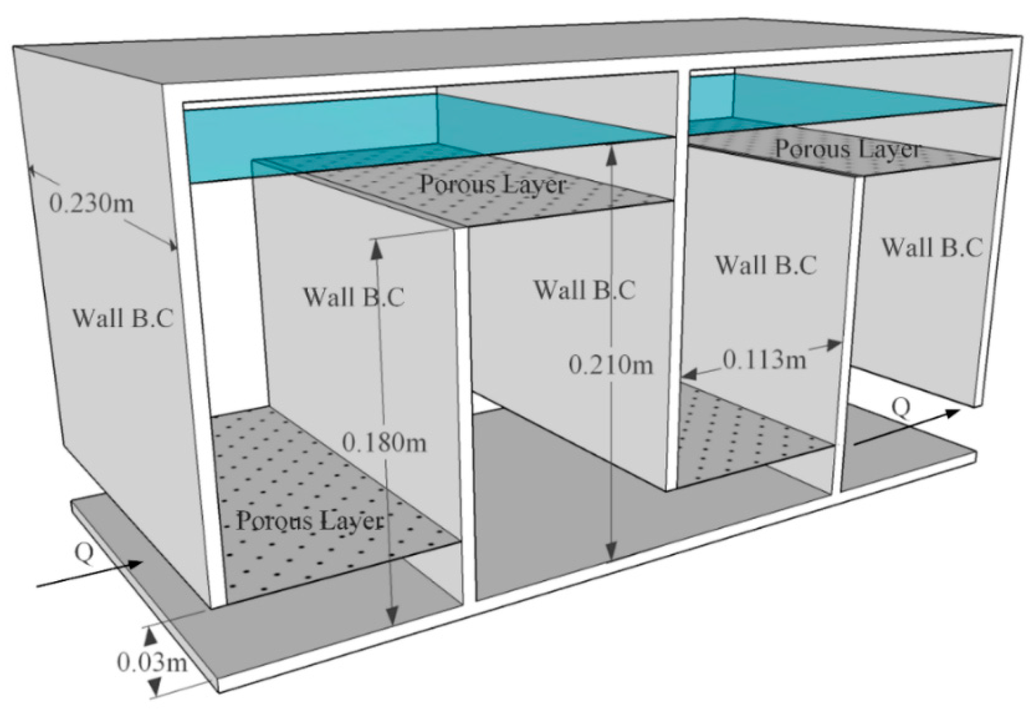
Standard baffle configuration utilises 3 or 4 equally spaced vertical baffles T12 where T is the internal tank diameter. Increasing the size or number of baffles beyond this point does little to increase the effectiveness of the mixing. In an effort to address this question a carefully conceived parametric study consisting of 30 high-resolution two-dimensional planar simulations was conducted to quantify the hydraulic efficiency of a laboratory scale tank as a function of dimensional relationships between key baffle design dimensions baffle opening length Lbo baffle channel width Wch and baffle channel.
Request PDF Hydraulic design of baffles in disinfection contact tanks This study focuses on understanding the hydraulic design of baffled contact tanks using computational fluid. Because the baffle forces fluid to remain in the tank longer more time is given to settle out water and particles. Two rectangular contact tanks were used both of which are assumed to be representative of disinfection tanks for small municipalities throughout the.
Replacement Cap with Chain. Fluid disturbances are commonly called sloshing and cause a number of issues such as breather damage short-circuiting diffusion and entrainment. Locate the inlet tube under a substantial depth of oil to avoid vortexes or add vanes to the throat of the tube extending outward.
For use with TFA005715 and BC40. Hydraulic Tank Baffle Design. H Water depth L Length of the flocculator channel S Space between baffles T Thickness of the baffles B Perpendicular center to center distance between baffles.
October 20 2014 By Josh Cosford. Hydraulic oil in mobile equipment reservoirs has disturbances caused by the motion of the equipment. The standard baffle design parameters are as follows.
To help cool return fluid it should be. Finished with power coating inside andout Lids. The partition forces the returning fluid to travel farther around the tank before.
5 t 1030 min contact opputinity in the basin small l arg e floc t 10 30 min small l arg e floc G light dense floc Gt 10 5 contact opputinity in the basin 10 -75 sec -1 10. I did a search for existing threads but not much was there. Baffles and inlets are assessed in depth using both physical tracer studies and computational fluid dynamics CFD simulations.
A properly designed reservoir has internal baffles to prevent excessive sloshing of the fluid and to put a partition between the fluid return line and the pump suction line.
Water Free Full Text Effect Of Porous Baffles On The Energy Performance Of Contact Tanks In Water Treatment Html

Hydraulic Tank Design And Work Basic Stuffworking Com
Hydraulic Tank Design And Work Basic Stuffworking Com

What Is Reservoir Definition Importance Construction

Why The Tank May Well Be A Hydraulic Fluid S Best Friend

Hydraulic Reservoirs Fluidsys Training Centre
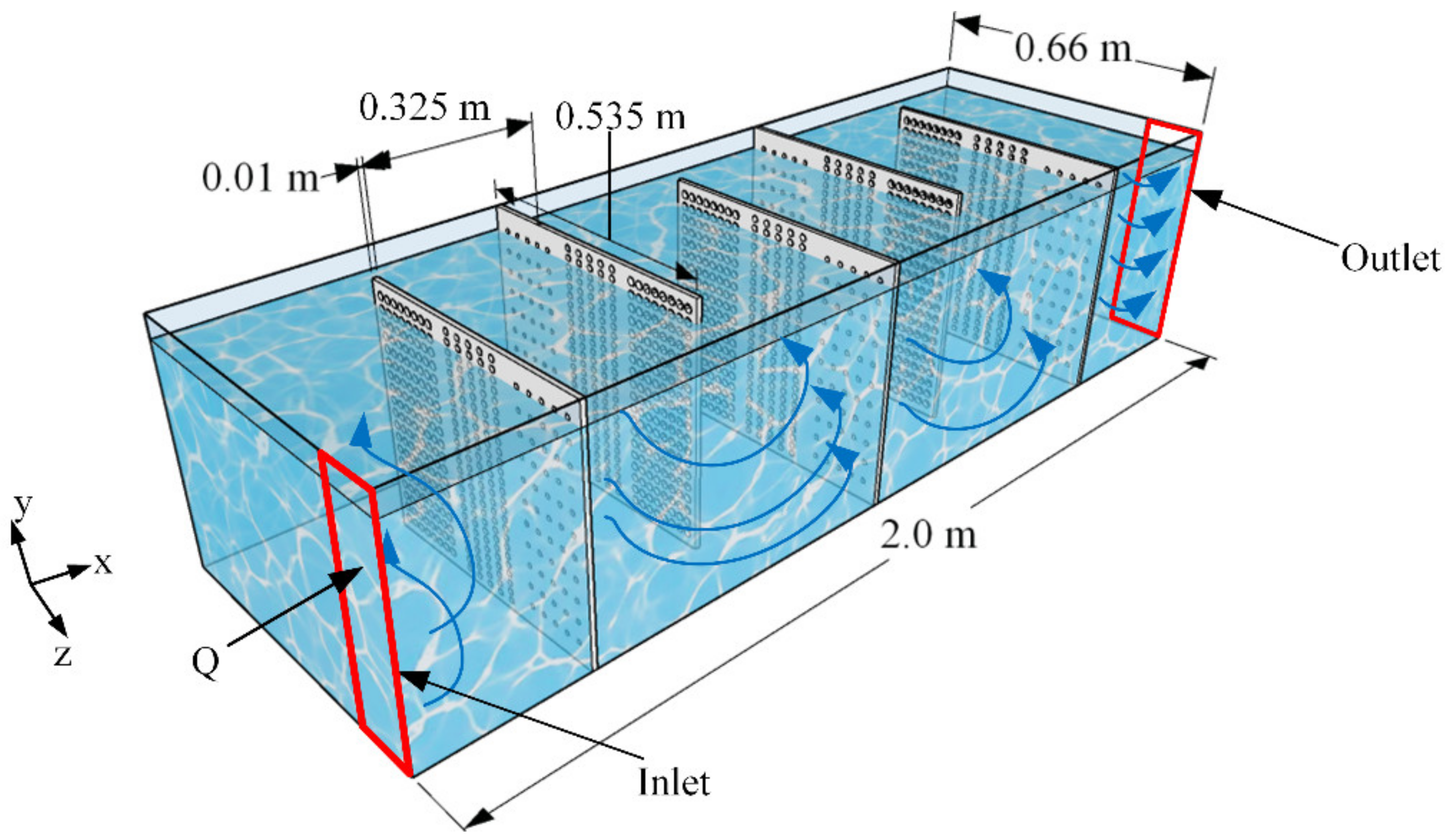
Water Free Full Text A Perforated Baffle Design To Improve Mixing In Contact Tanks

Novel Slot Baffle Design To Improve Mixing Efficiency And Reduce Cost Of Disinfection In Drinking Water Treatment Journal Of Environmental Engineering Vol 143 No 9
0 comments
Post a Comment